Custom Valve Lighthouse 2.0 Tracker Research Project 2020
The goal of this research project was the understand and recreate the tracking system implemented by Valve with the gen2.0 lighthouses.
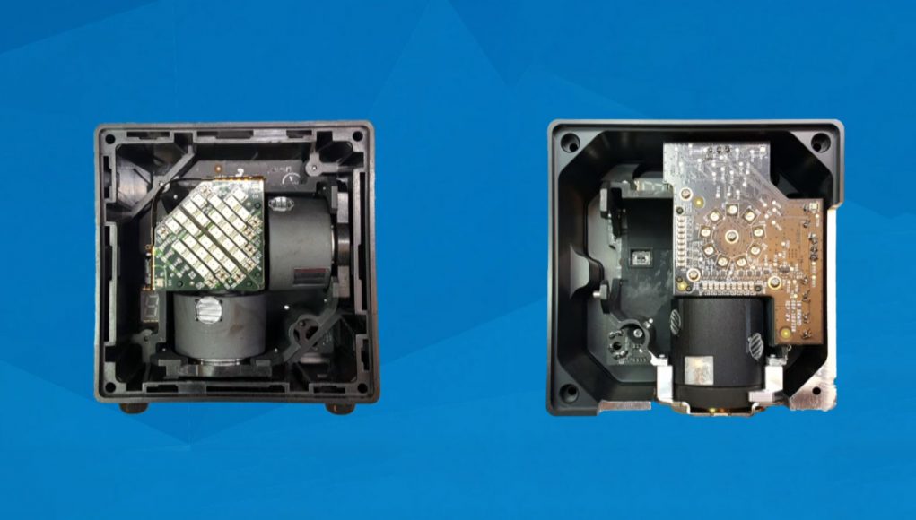 gen1.0 lighthouse internals (left) and gen2.0 lighthouse internals (right)
The older gen1.0 lighthouses utilized two rotors with IR emitters on them, as well as a bright wide angle IR emitter. Trackers could determine their location relative to the lighthouse based on a flash-sweep method. It sends out a bright flash to all the sensors in the area. And then passes a sweep (either horizontal or vertical) over the sensors immediately following the flash. The trackers determine the time between the flash and the corresponding sweep to determine what angle that sensor is in relation to the lighthouse. With two lighthouses (which requires syncing between the two) and some sensor geometry, one can determine a position in the area of covered by the lighthouses.
With gen2.0 lighthouses, there is only a single rotor and NO flash cycle. The sensors have increased accuracy, and do not require syncing between lighthouses (tracking can be achieved with a single lighthouse). The two major changes that allow this are that data is now encoded into the sweep IR, and the IR emitters that were providing the horizontal or vertical sweeps in the gen1.0 model are now on the same rotor with a 90 degree offset from each other.
From the lighthouse side of things, a Linear Feedback Shift Register has been implemented to generate a very long, unique, and eventually cyclic bit sequence. It uses a 20bit tap sequence that represents a polynomial for generating the output bit sequence. The 20bit tap sequence determines which bits from the active lfsr sequence get XORed to determine the next bit. That bit is fed into the shift register, and the first bit gets popped off (and becomes the next bit of the output sequence). The lighthouses have 16 channels, and each channel has 2 polynomials that are used in an alternating fashion for every other full rotor rotation. After the LFSR is determined, the data is encoded with Differential Manchester Encoding (also known as Biphase Mark Code). This converts one bit into an edge (or no edge). A bit value of 0 is converted into an edge, and a bit value of 1 is converted into no edge. There is also always an edge between each bit.
From the tracker side of things, the IR sensor passes information to the TS4231 chip by Triad Semiconductors. The TS4231 needs to be reconfigured on every power cycle in order for it to work with gen2.0 lighthouses. It has two lines: data and envelope. The data line passes the diff manchester encoded data back to you. The env line drives low when the IR sensor senses a sweep to tell you that the current data is live. The data line can drive numbers when the env line is high, but those should be ignored as they are not valid data.
The firmware for the tracker needs to capture the data coming from the TS4231, which is where a significant amount of the issues come into play with my implementation. Most consumer products I can find utilize an FPGA to capture and decode the data from the TS4231, however for my implementation I went for an approach without an FPGA. I tried a few different boards, but settled on the Adafruit Feather M0. It has a 48 MHz clock and an event system that I can trigger and input capture timer to count the time between edges on the data line. Originally I tried using this with reading and writing to the pins, but that proved too slow. The LFSR on the lighthouse is generating the bit sequence at a rate of 6 MHz, and after encoding the final data speed being sent over IR is 12 Mhz. This means that I have 83 nanoseconds to read and store a bit of the data. The Feather M0 has an input capture on a timer that I trigger with data edges. This will count the time between each edge. Since the diff manchester encoding has an edge between every bit, it is fairly easy to convert from pulse length to decoded bits. Each bit will be represented by a 166 nanoseconds stretch. If there are no edges in that time period, its a ‘long’ (no change. bit value of 1). If there is an edge in that time it will look like a ‘short-short’ (change, bit value of 0). This saved me a lot of time, but still wasn’t fast enough as the storing of the output from the input capture timer was taking too many cpu cycles to execute. This was remedied by setting up a Direct Memory Access (DMA) to automatically take the output of the input capture and store it in memory. With this I was able to measure a ‘short’ (83 nanosecond pulse) with around 4-5 counts on the timer. This could likely be increased to reduce the introduction of noise by reconfiguring the DMA and timer to run off an optional 96 MHz clock, but I was not able to implement that yet.
Once the slow data is captured. There is a large enough time as the rotor spins back to its initial position that the data can be interpreted. First step is to determine what polynomial is being used. This is a fairly intensive process that loops through different known polynomials and uses an LFSR to try and generate a sequence of bits that matches the captured data. Once the polynomial is determined, you can then reference how many iterations into the LFSR it took you to get to that bit sequence in order to determine the angle of the sensor from the lighthouse. From there the process of determining sensor geometry and calculating your position from the lighthouse is the same as it was with gen1.0 lighthouses.
I was unable to get a complete package, single program working that handles all of these processes. I was able to implement individual pieces but am still working on combining them together. You can see more information about the pieces on the github.
Things that need to still be done:
- finalize DMAC config on feather for proper data capturing
- pass feather data to live decoders
- ensure live decoders can determine polynomial in the time between full rotations
- find sweep angles using polynomial + lfsr + live data
- convert sweep angles to positions (potentially handled by other libraries like LibSurvive)